Welcome to REAL WORLD CYCLING
Our SEARCH BAR is optimized to find what you need quickly. Enter the name of your bike frame, the first few numbers of a bearing, or description of any part!
RWC NEEDLE BEARING INSTALLATION, SANTA CRUZ 5010 V1
08/02/2018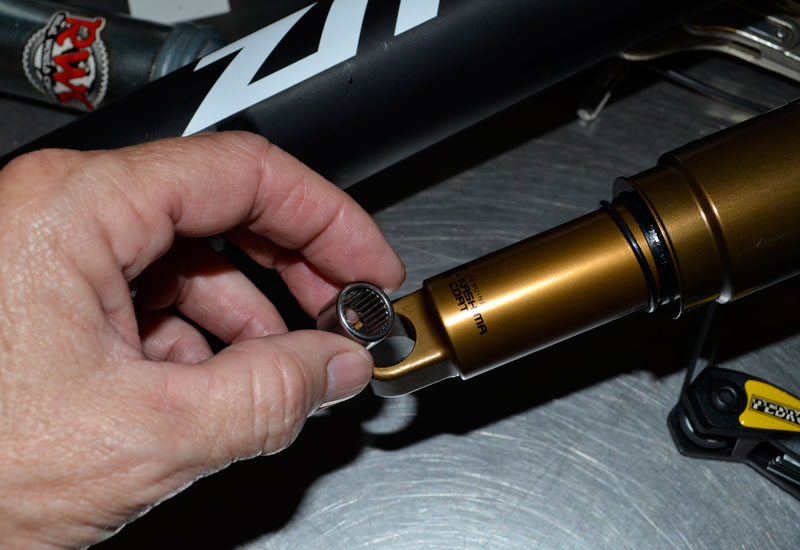
INSTALLATION INSTRUCTIONS
FOR
RWC NEEDLE BEARING KIT
SANTA CRUZ 2016 5010
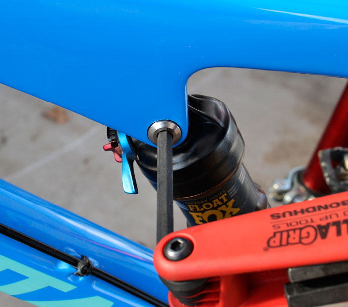
1) Loosen the rear shock mounting bolt by turning it counter-clockwise:
It's recommended that you properly support the bike in a sturdy stand of some sort.
2) Support the rear triangle of the frame as you remove the bolt:
Lifting up on the rear wheel will take the weight off the bolt, allowing you to pull it out. After the bolt has been removed, gently lower the rear wheel.
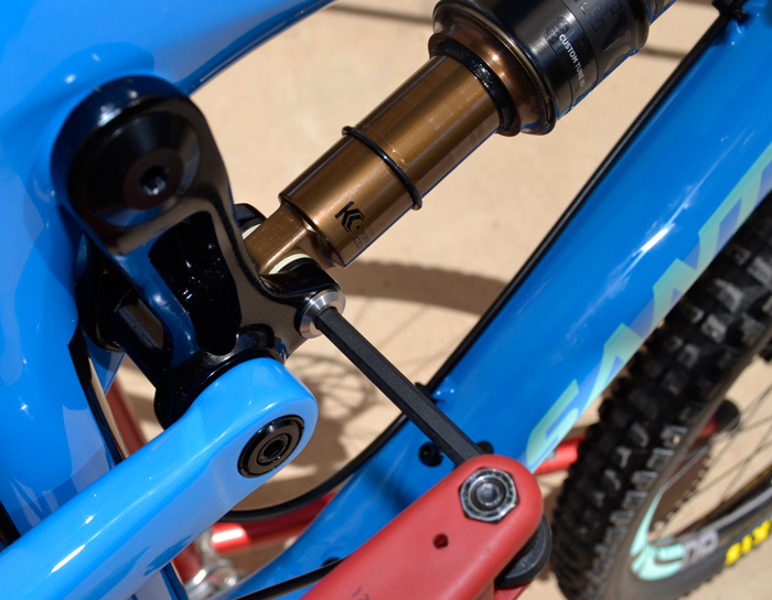
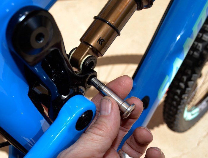
3) Loosen the front shock bolt by turning it counter-clockwise:
It should go without saying, but be sure to hold onto the shock when you pull the bolt out!
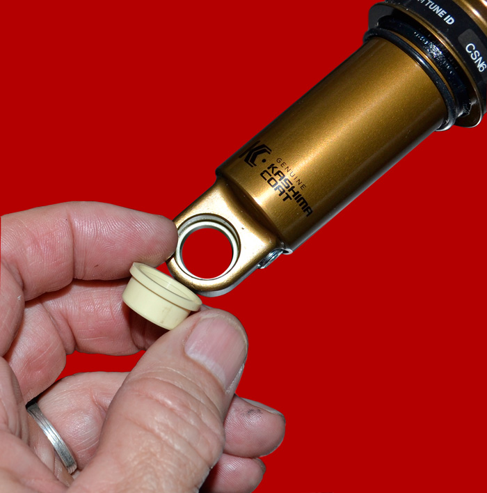
4) For the plastic bushing system, pry off the black outside spacers (shaft end of the the shock only):
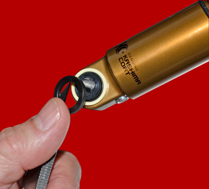
After prying the spacers off, you can also remove the small O-rings from the bushing faces.
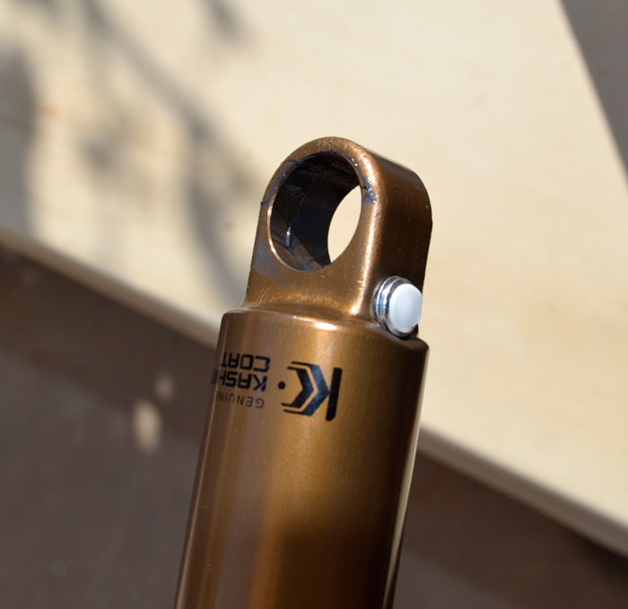
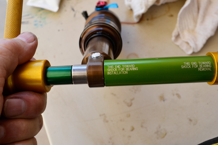
5) Use the RWC tools to partially remove the center pin:
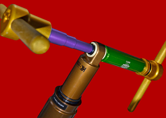
In certain applications, the center pin may be extracted from the plastic bushings by hand. However, it's normally a pretty tight fit. While the "DU Pilot" is primarily designed to remove internal DU bushings, it can be used in conjunction with our Needle Bearing Tool to partially press out the center pin, as illustrated above. Properly orient the green bearing tool with the large opening toward the shock. This is clearly marked on the back of the tool: "THIS END TOWARD SHOCK FOR BEARING REMOVAL." The bearing tool is not deep enough to accept the entire pin, so the idea is to just push it part way out.
6) While twisting, pull the pin the rest of the way out of the bushings:
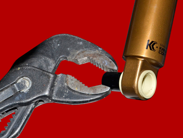
If loose enough, pull the pin the rest of the way out by hand. If necessary, you can use pliers. If you want to save the pin for future use, you can pad the plier jaws with a cloth or other suitable material.
7) CAREFULLY use a utility knife (or similar) to get under the bushing flange:
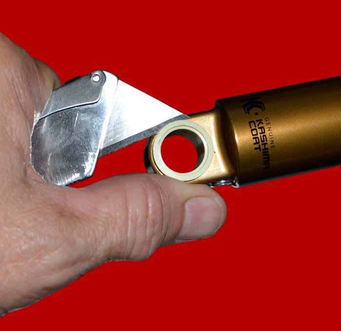
A sharp blade is not necessary for this step. In fact, a dull blade might be more desirable in case you slip... Work around the flange in a circle, gently prying upwards to gradually remove the plastic bushing.
8) When the first bushing is out, turn over the shock and repeat the procedure for the remaining bushing:
9) Grease the inside of the now empty shock eyelet bore:
It's always a good idea to lubricate any press-fit assembly. It's especially important when working with dissimilar metals. Our grease of choice for this application is Rock 'n' Roll® Super Coat Grease. You could also use an anti-seize compound.
10) Remove the plastic needle roller retaining sleeve from the new needle bearing and place the bearing on the green RWC pilot tool:
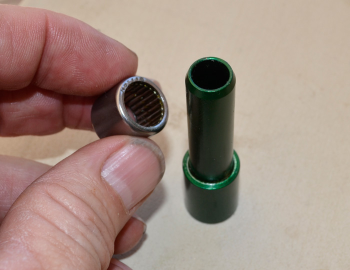
This is a "MAX" bearing, also known as "full-complement." The cup has been completely packed with all of the roller elements that will fit. No type of roller cage or retainer is used in a MAX bearing. This increases it's load capacity significantly. However, the needle rollers CAN FALL OUT. Normally, the grease and surface tension hold them in the cup just fine. And, should some of them fall out, they can be re-inserted into the cup without any problem. However, if they happen to fall out and you are not prepared for it, you could potentially lose some of the rollers, and that would be a problem (we can send more).
11) Orient the tools as shown. Slowly tighten the assembly. The bearing will press in easily. Stop when you feel the bearing bottom against the green tool face:
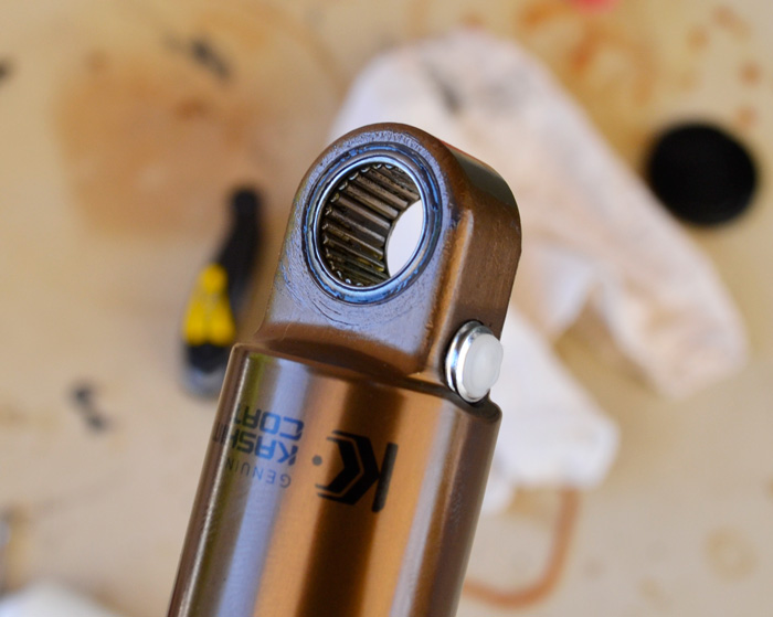
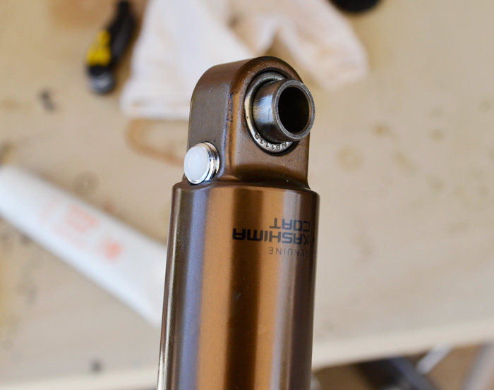
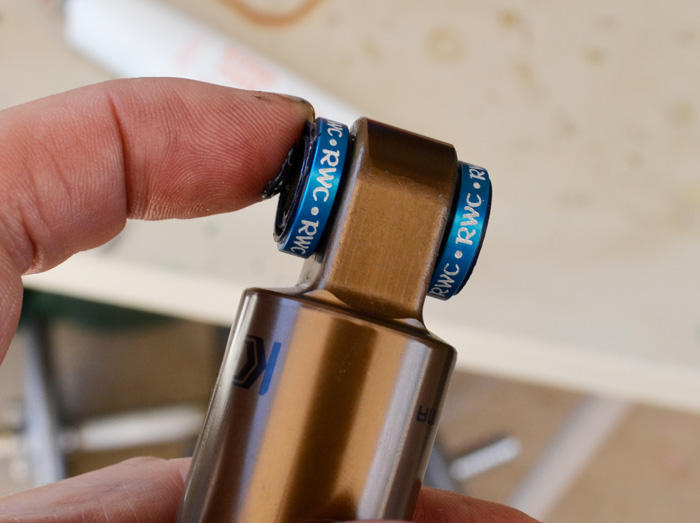
12) The bearing body should be flush with the shock eyelet on each side:
13) Each kit contains at least THREE (3) inner rings (axles). The outside diameters of these inner rings vary slightly. They are in separate
bags marked "++", "+", "-", and so forth. KEEP THESE INNER RINGS IN THEIR RESPECTIVE BAGS as they are impossible to
visually tell apart. Take them out only one at a time and put each one back into its respective bag before taking out another.
Whichever inner ring you end up using SAVE THE OTHER RINGS IN THEIR MARKED BAGS FOR POSSIBLE FUTURE USE.
FOLLOW THIS PROCEDURE TO FIND THE PROPER INNER RING FOR YOUR PARTICULAR APPLIATION:
a) Carefully attempt to guide the largest OD inner ring (marked “++”) into the installed needle bearing.
b) If the “++” tolerance inner ring fits inside the rollers and you can rotate it without any binding, you may proceed to the next step.
c) If the “++” inner ring does not fit inside the rollers or feels very tight or rough, return it to its bag and attempt to install the "+" inner ring.
d) If the "+" inner ring fits inside the rollers and you can rotate it without any binding, you may proceed to the next step.
e) If the "+" inner ring does not fit inside the rollers or feels very tight or rough, return it to its bag and install the "nominal" inner ring, if
your kit has one. If not, install the "-" inner ring.
By following these steps, you will find the perfect fit regardless of the eyelet bore tolerance variation of your particular shock:
Please not that some "bedding in" of the needle rollers may take place after the first couple of rides, after which you may need to install a larger OD inner ring.
For this reason, please keep the inner rings that you did not use in a safe place.
14) Lightly grease the inside seals of each spacer:
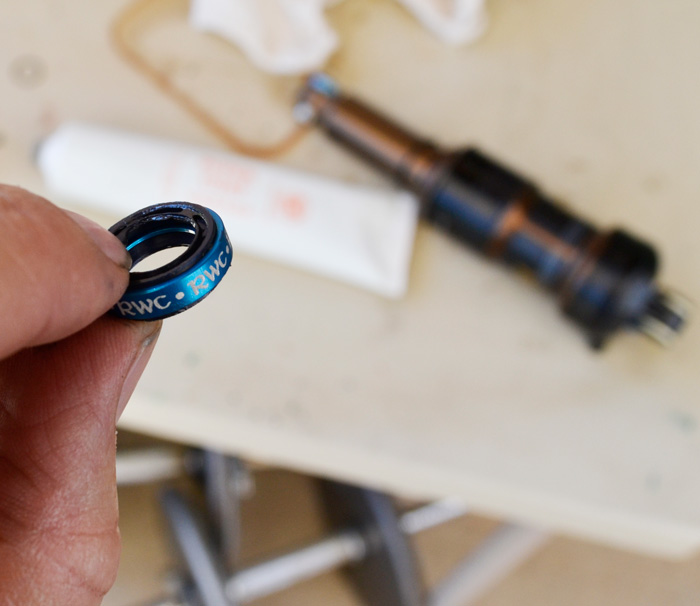
15) Place the spacers onto the inner ring and slide them against the shock:
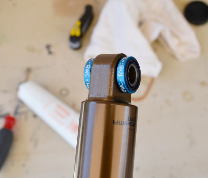
16) Lightly grease the outer spacer seals:
17) Apply Blue Loctite to the threads of one of the shock mounting bolts:
.jpg)
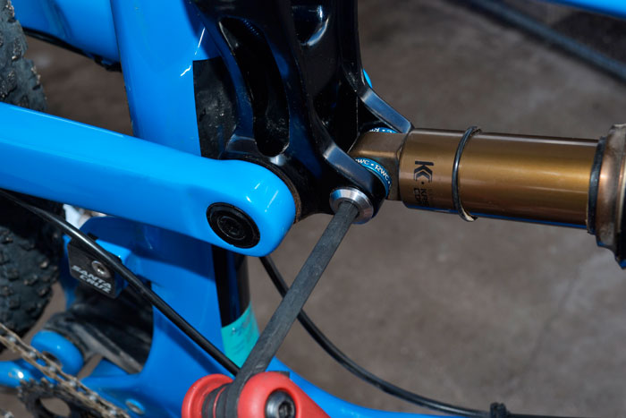
18) Slide the air can end of the shock into the top tube mounting tabs and install the mounting bolt:
Recommend torque value is 140 INCH/LBS
19) Apply Blue Loctite to the threads of the remaining shock mounting bolt:
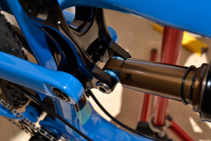
20) Raise the rear triangle of the frame as needed to align the shock eyelet with the swing link shock mounting tabs.
Install and tighten the shock bolt:
Recommend torque value is 140 INCH/LBS
21) Check for proper sag settings. You may need additional air in the shock now that friction is no longer affecting the shock stroke.
Enjoy the improved small bump compliance!
Please don't hesitate to contact us with any kit sizing questions or service part needs. Individual replacement parts are available. Our tools are designed to do the job quickly and easily without risk of damaging the parts or the shock. However, you are welcome to use whatever tools or improvised methods you prefer. Having said that, please be advised that we will not be responsible for the results of your improvised tools. If you do have any installation problems, you will find that we are willing to help you make things right regardless of where the fault lies. As with all of our products, satisfaction is guaranteed.