Welcome to REAL WORLD CYCLING
Our SEARCH BAR is optimized to find what you need quickly. Enter the name of your bike frame, the first few numbers of a bearing, or description of any part!
RWC NEEDLE BEARING INSTALLATION, EVIL THE FOLLOWING V1
05/28/2019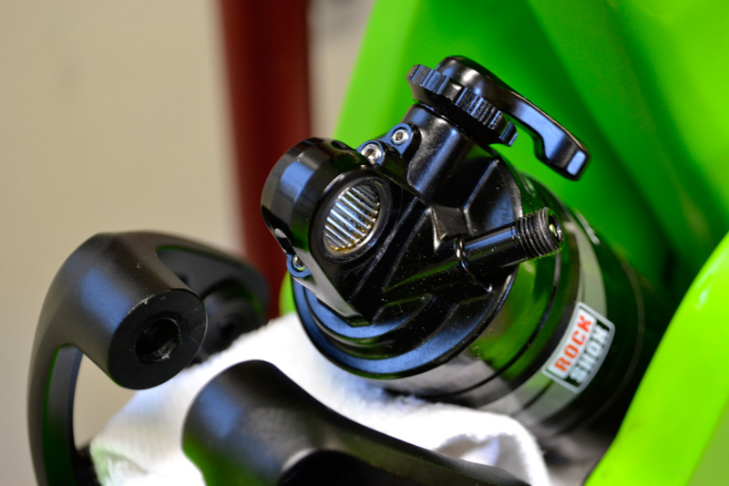
RECOMMENDED TOOLS AND SUPPLIES
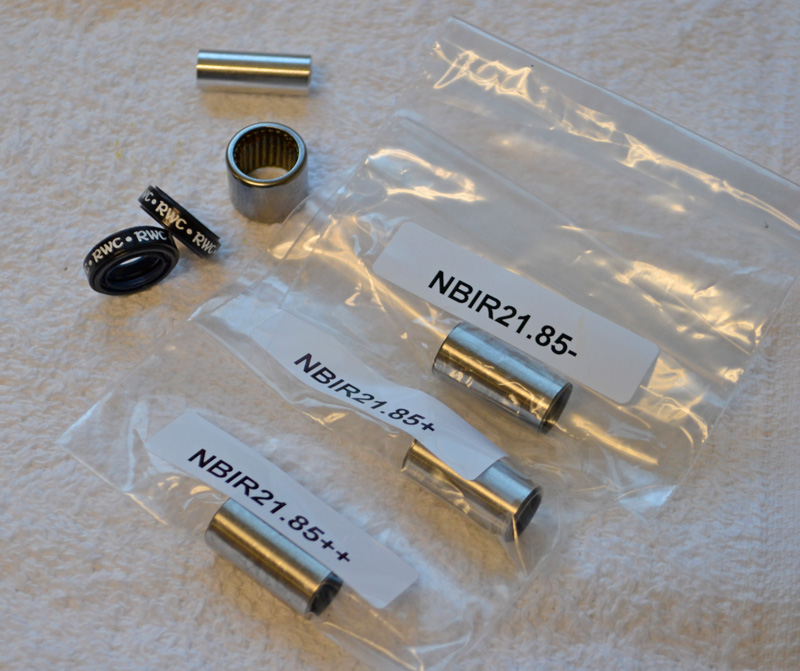
for installing NBKRWC2185 Shock Eyelet Needle Bearing Kit
in EVIL BIKES "THE FOLLOWING"® V1
-5mm Allen wrench
-RWC DU Needle Bearing Tool
-RWC DU Bushing Pilot
-Press Handle Set w/8mm threaded rod
-”Channel-lock” pliers
-Torque wrench w/adapter and Allen bit
-Clean shop towels
-“Super-Coat” or similar grease
-Blue Loctite
-Shock pump
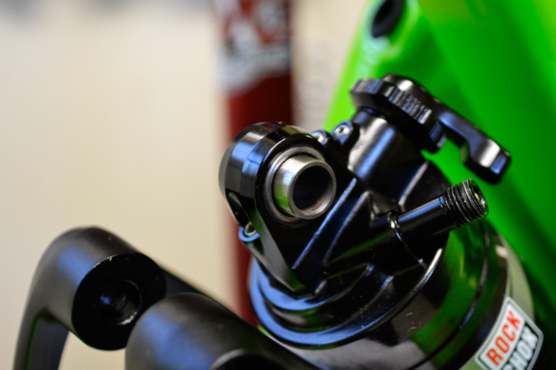
1) PREPARE FOR POSSIBLE OIL
SPRAY and depress the Schrader
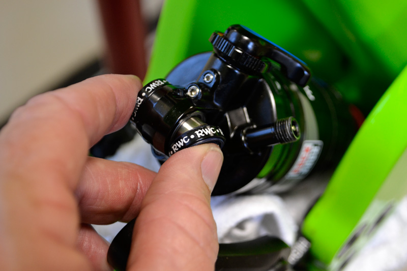
valve core to release the air
pressue from the shock.
NOTE: You might want to write down the
current shock air pressure that you are
running.
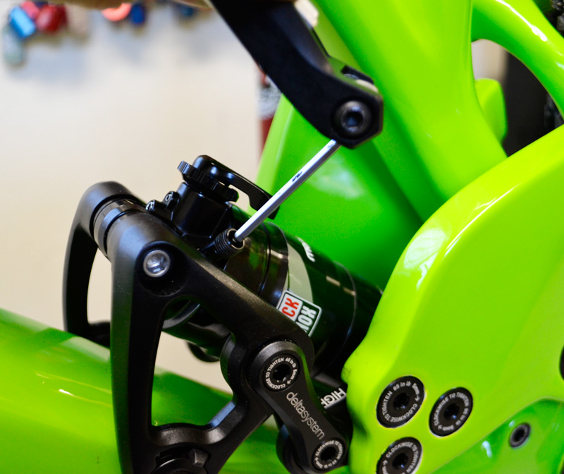
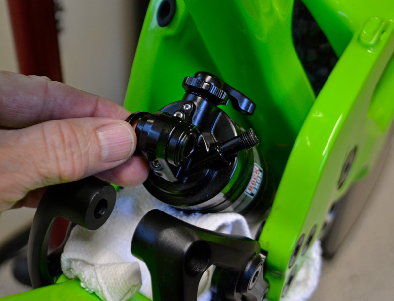
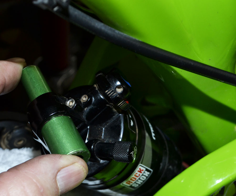
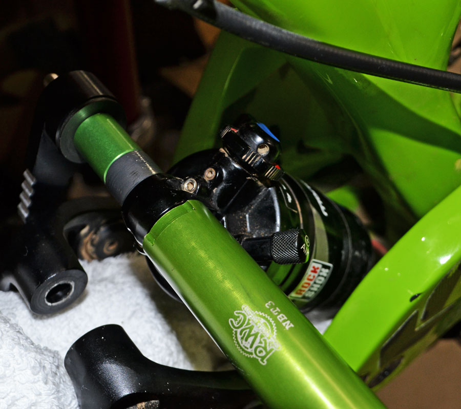
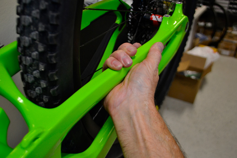
2) WHILE SUPPORTING
THE REAR TRIANGLE OF
THE FRAME, use the Allen
wrench to remove the upper shock mounting bolt.
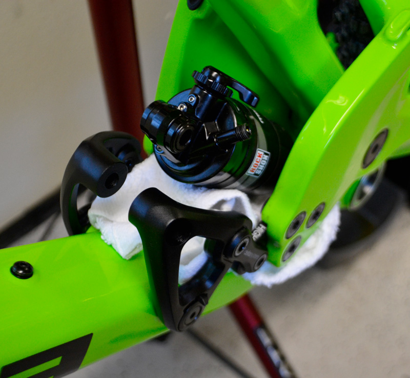
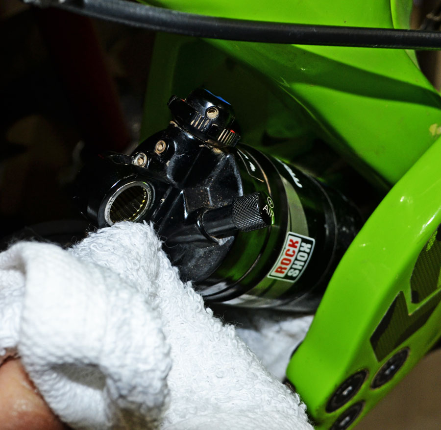
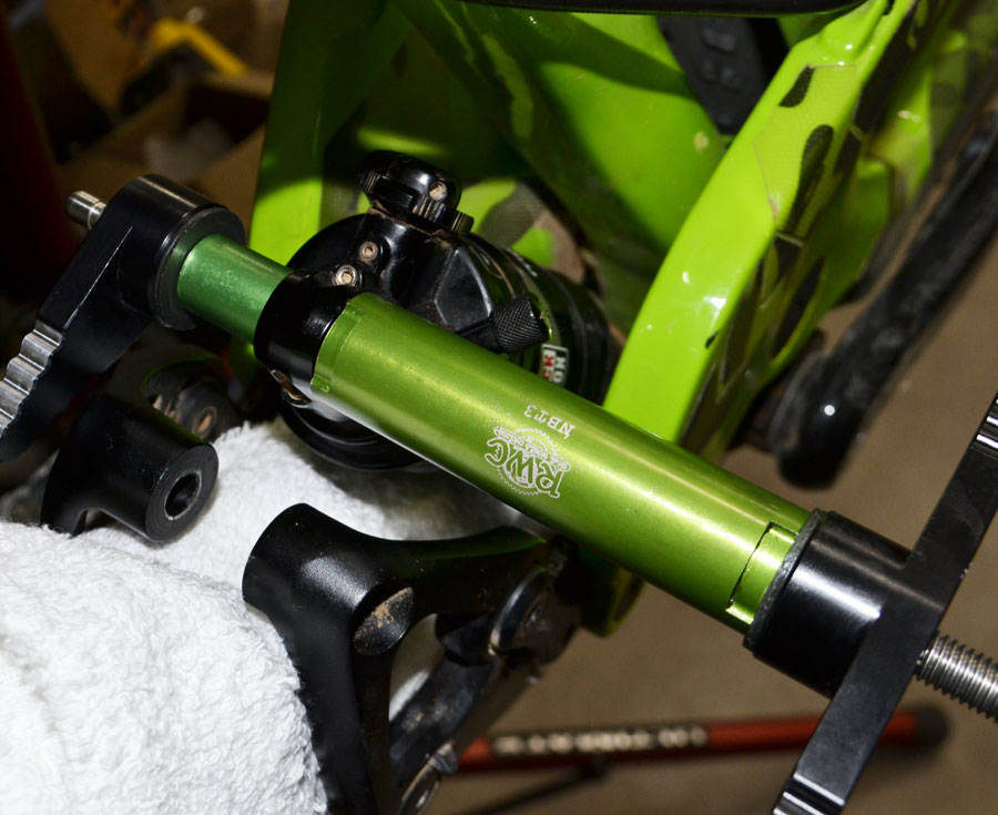
3) Place a shop towel
under the shock, as pictured to hold the shock
in place and to protect
the frame’s paint.
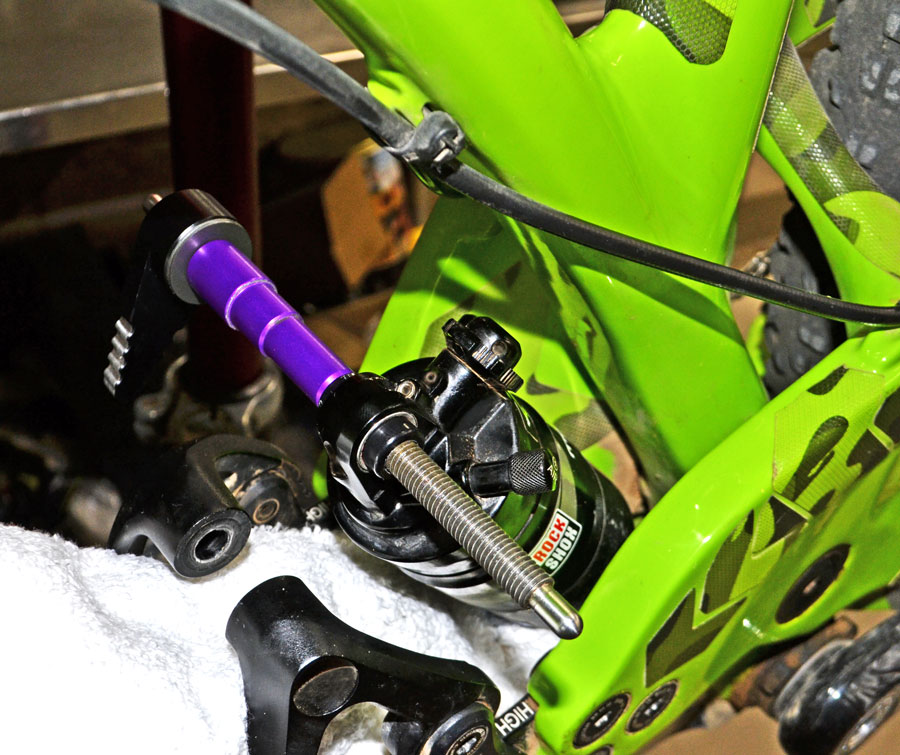
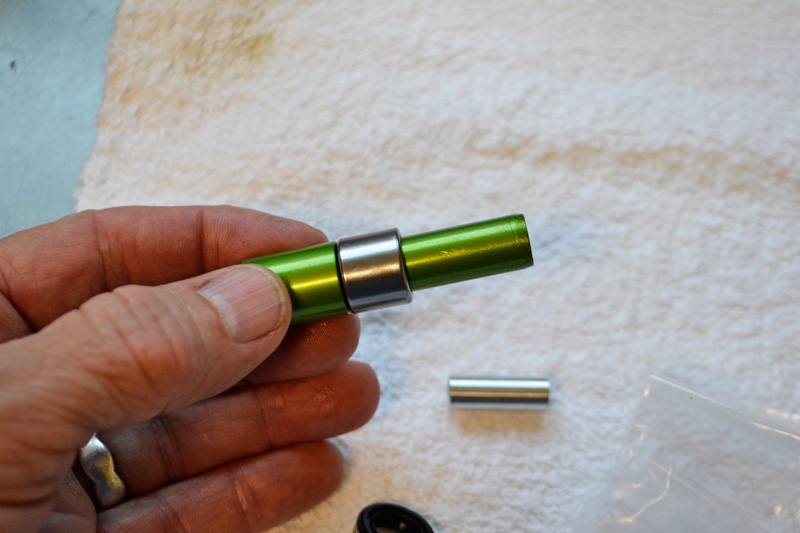
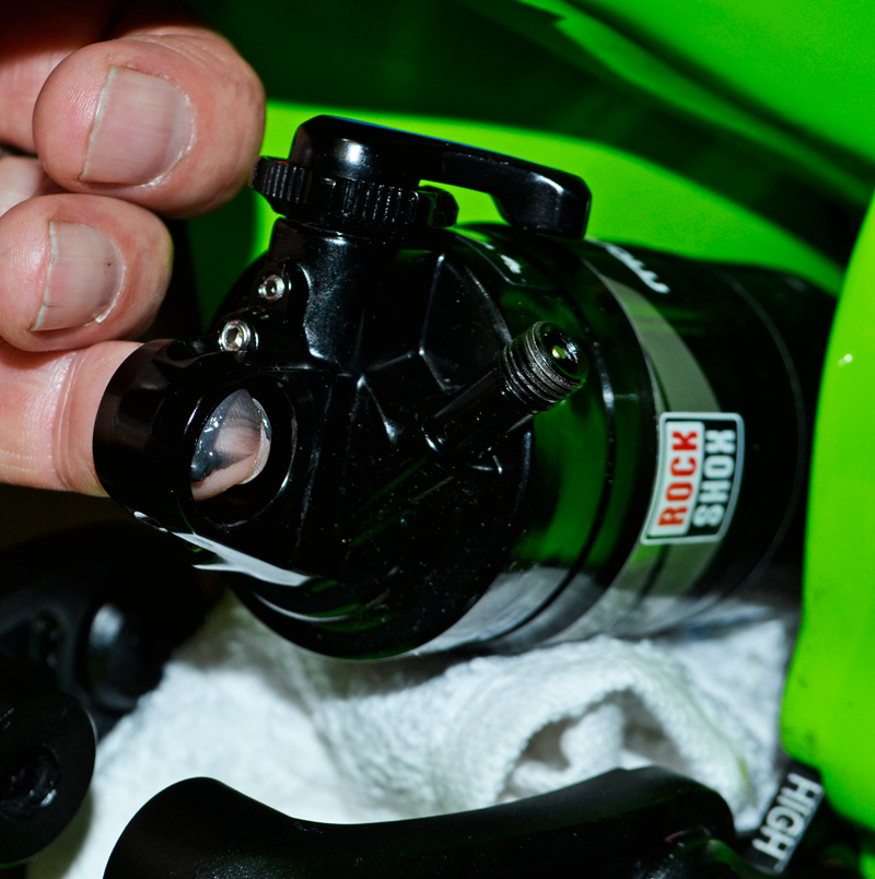
4) Remove the spacers and seals from the shock thru-pin.
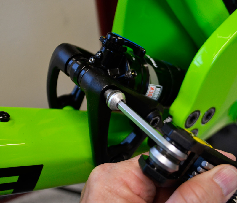
5) Place the DU Bushing
Pilot onto the handle set
and slide the threaded
rod through the shock
thru-pin.
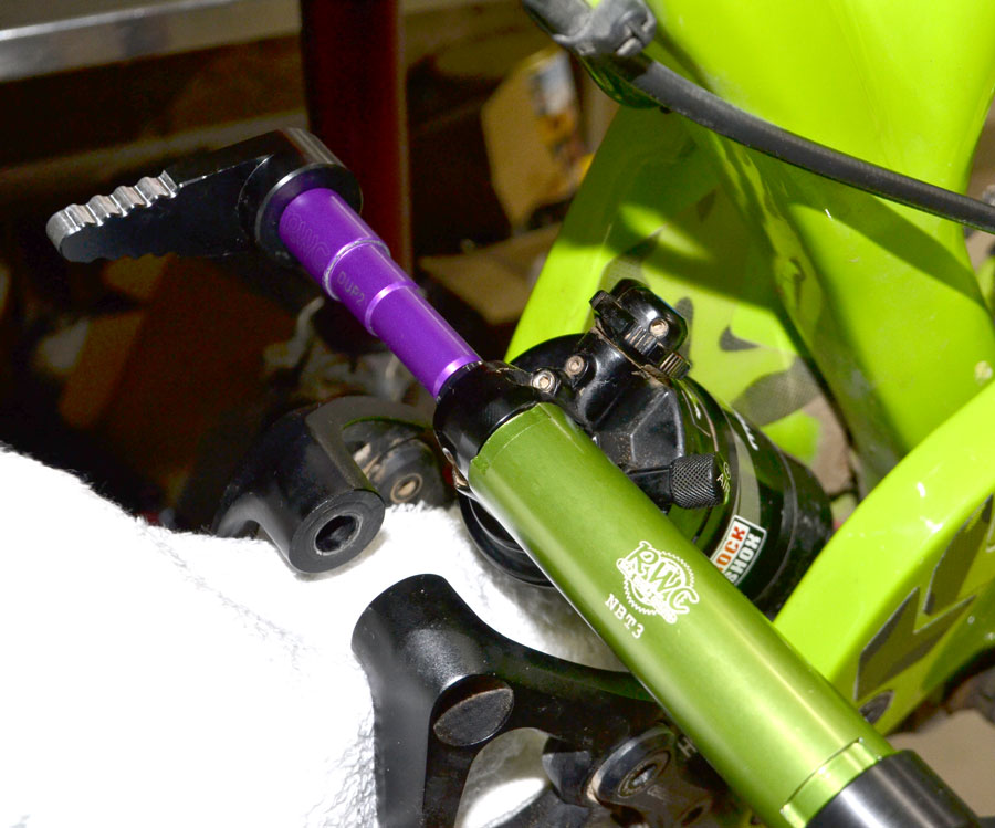
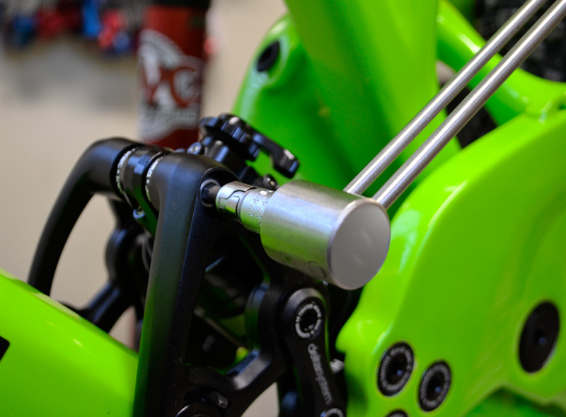
6) Slide the RWC Needle Bearing Tool onto the threaded
rod of the press handle set.
Be certain that the larger
opening on the tool is facing
toward the shock. Put the
other handle onto the threaded rod and wind the handles
toward each other until you
feel the thru-pin bottom out
inside the green receptacle.
Then, remove the tools and
you’ll find the pin partially
removed.
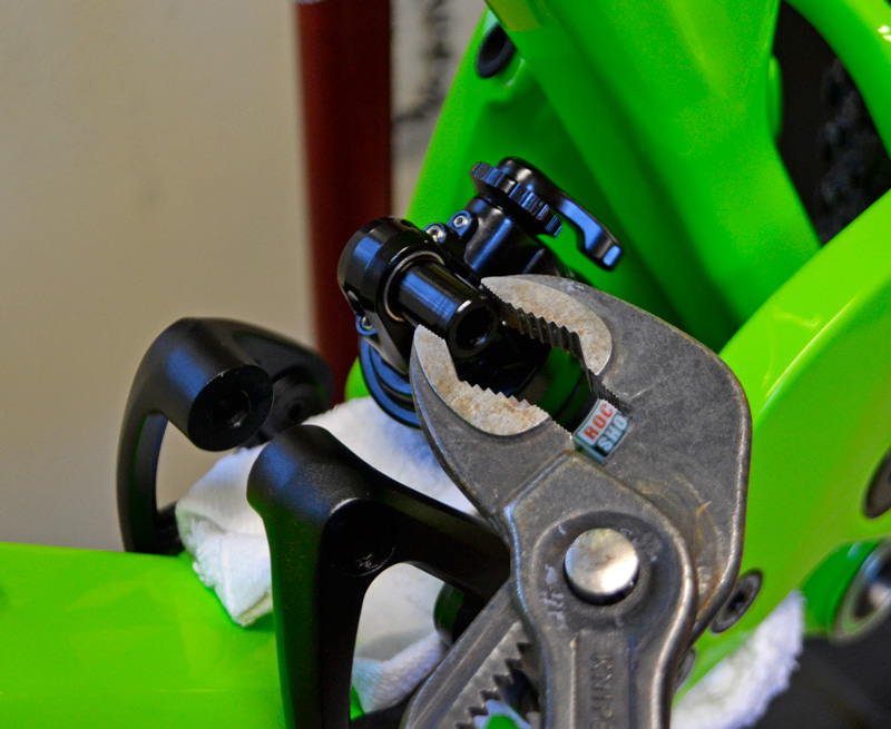
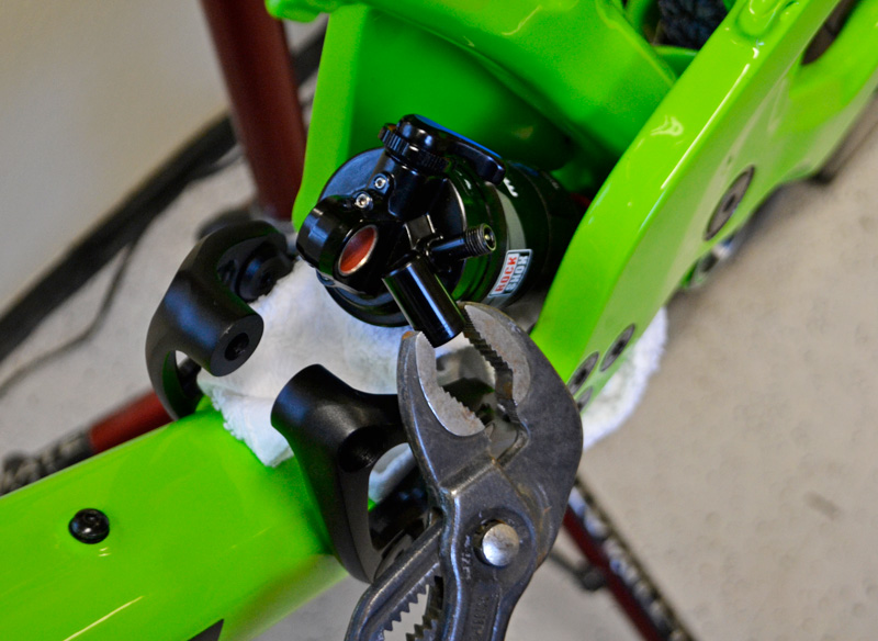
7) Use channel-lock pliers to
grip the end of the partially
removed thru-pin. Twist back
and forth with the pliers as
you pull the pin the rest of the
way out of the shock bushing.
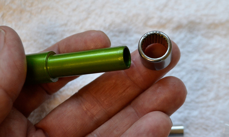
With the thru-pin removed, you can see the
metal bushing that is inside the shock eyelet. This
metal bushing is usually
coated with a red colored
dry lubricant coating. THIS
BUSHING MUST BE REMOVED.
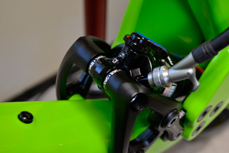
8) Place the DU Pilot directly inside the bushing and place the needle bearing tool on the opposite side of the shock. Face the larger of the two openings in the tool toward the shock.
Thread the opposite handle onto the threaded
shaft and wind out the
bushing.
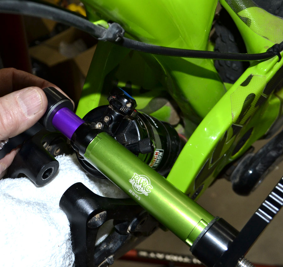
In the picture below you can see the
removed bushing. With the
bushing removed,
you now have a bare shock eyelet bore
that is ready to receive the needle
bearing in place of
the bushing.
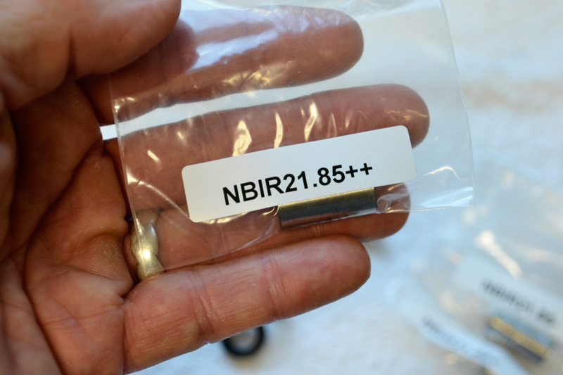
NOTE: There is only one Real World
Cycling shock eyelet needle bearing kit. As with all successful products, others have made attempts to
copy our kit. The fact is, no other
needle bearing kit has the level of
engineering put into our kit. Our
kit contains multiple bearing inner
rings (“axles”) of varying Outside
Diameters to account for the machining tolerances of your shock
manufacturer. This guarantees a
proper fit with YOUR shock.
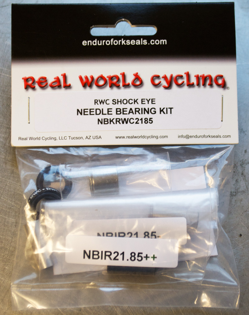
KEEP ALL OF THE INNER RINGS THAT YOU DON’T USE IN A SAFE PLACE WHERE YOU CAN FIND THEM LATER. You may need a larger or smaller OD inner ring in the future. The aluminum sleeve is for use with 6mm mounting bolts and won’t be used in this application.
Because the inner
ring OD differences
cannot be discerned
by the naked eye, we
recommend that you
NEVER HAVE MORE
THAN ONE INNER
RING OUT OF ITS BAG
AT THE SAME TIME.
Most of the kits have
3 inner rings. Some
kits contain 4.
When you get ready to place the needle bearing onto the pilot, remember that this is a “MAX” bearing--it’s all rollers with no retainer cage. This makes it stronger, but remember that THE ROLLER ELEMENTS CAN FALL OUT!
9) Place the needle
bearing onto the
installation pilot.
10) Check the fit of the needle bearing with the shock eyelet. Attempt to slide the bearing into the eyelet by hand.
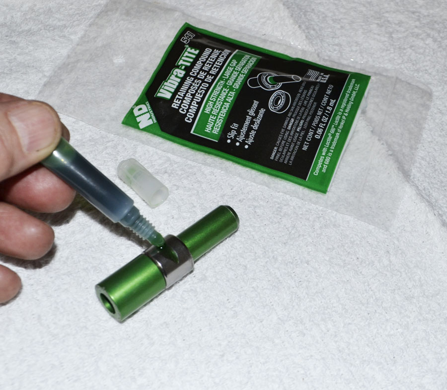
11) If the bearing will NOT slide into the shock eyelet by hand, skip ahead to step 17. If the bearing DOES slip into the shock eyelet by hand, apply some Vibra-Tite bearing fixative into the shock eyelet.
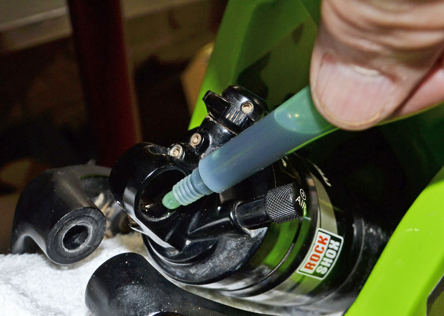
12) Spread the Vibra-Tite into an even coat inside the eyelet.
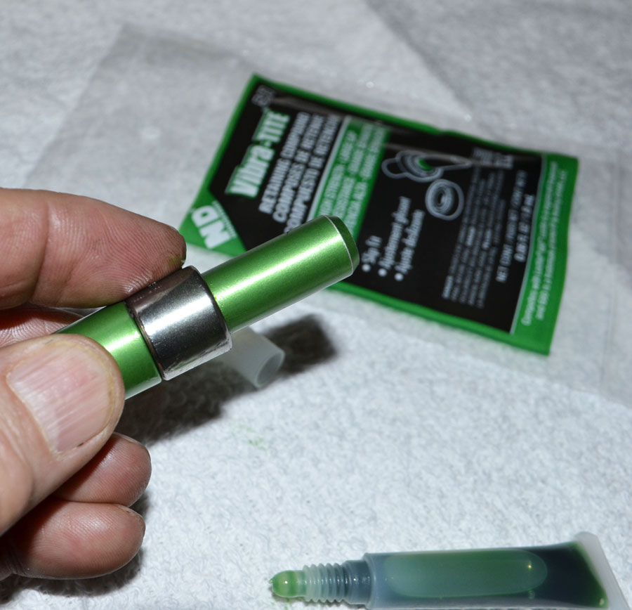
13) Apply some Vibra-Tite to the outside of the bearing cup.
14) Spread the Vibra-Tite evenly over the outer cup surface.
15) Push the bearing into the eyelet and center it.
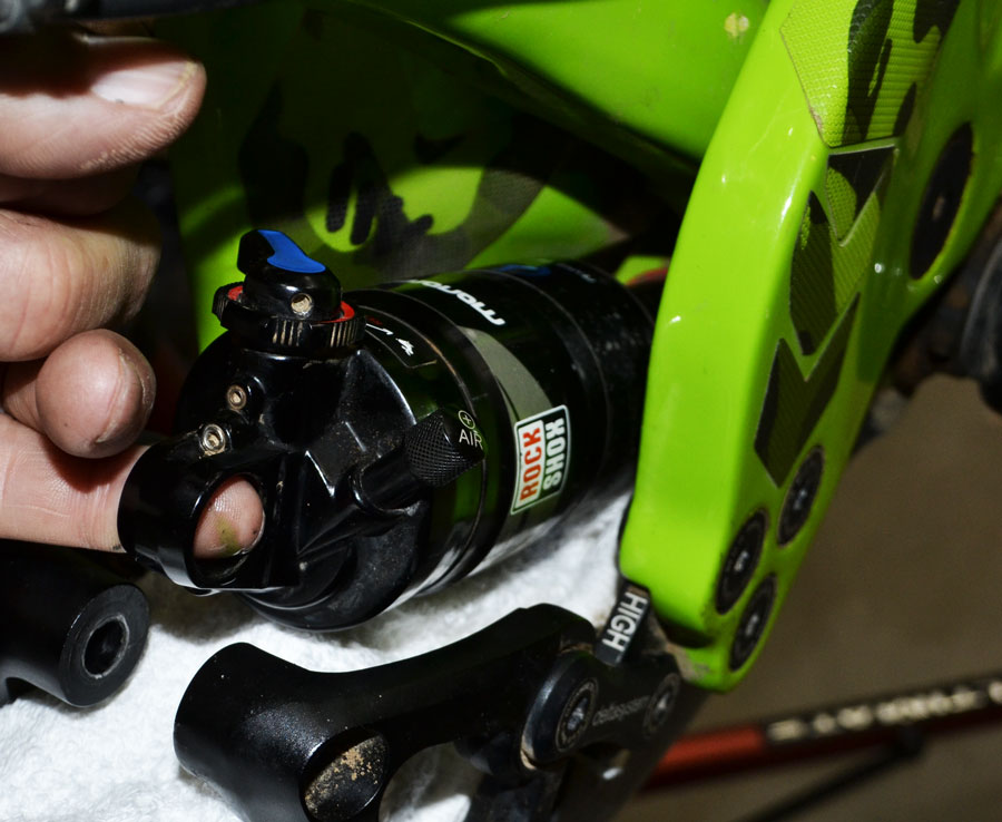
16) Wipe off any excess Vibra-Tite off the edges of the bearing, being careful not to get any inside the bearing. ALLOW FIXATIVE TO CURE FOR 24 HOURS and then skip ahead to Step 22.
17) Put some grease inside the shock eyelet.
18) Put some
grease on the
outside of the
needle bearing
cup.
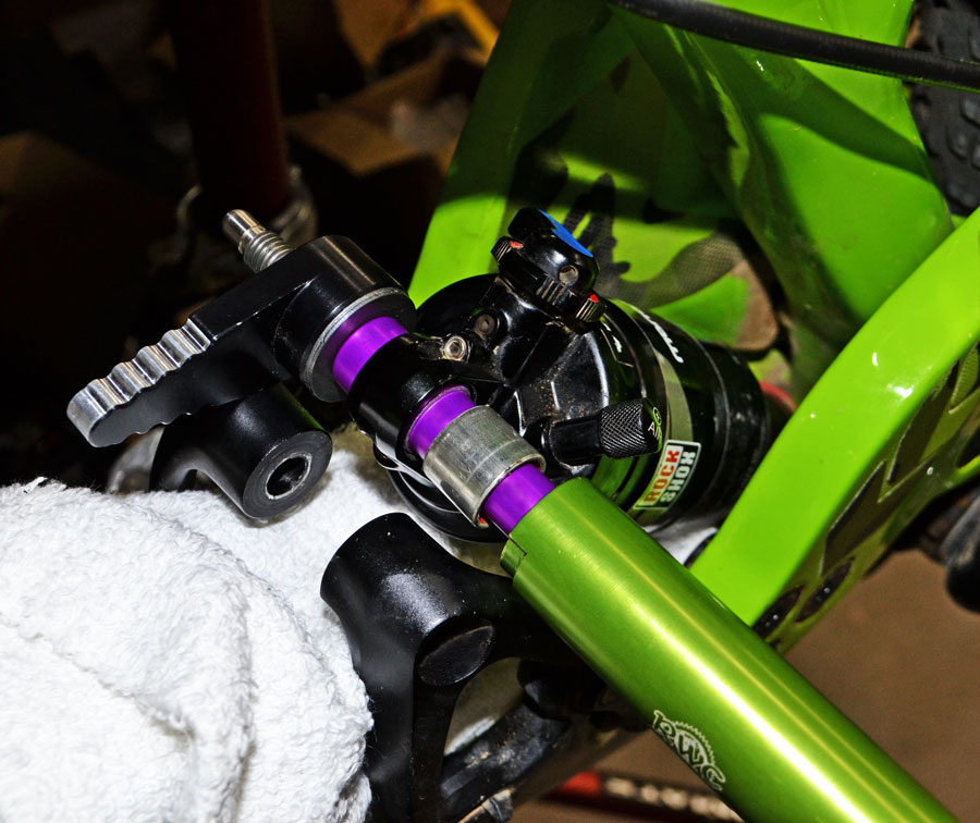
19) Configure the tools
as illustrated in the picture at the left. Orient
the female half of the
tool with the smaller
opening toward the
shock. The back side
of the tool is actually
marked to show you
which end faces the
shock depending upon
which operation is being
performed.
20) Tighten the
press handles
until you feel the
needle bearing
cup come to a
rest against the
female half of the
tool.
21) Remove the handle set and carefully remove
the pilot from the
bearing, remembering that the needle
rollers can fall out.
22) Start with the largest OD inner ring and
remove it from the bag.
KEEP THE OTHER INNER
RINGS IN THEIR RESPECTIVE BAGS so that you
can keep them properly
identified.
23) Attempt to slide the “++”
inner ring into the bearing. If
this inner ring goes into the
bearing and turns smoothly (no
binding), then you are ready
to move onto step 17. If the
OD of the “++” inner ring is too
large, move down a size and try
again. Continue this process
until you find the right fit. It is
possible that after a few rides,
the needle rollers will bed in
and you could require an inner
ring with a larger OD. For this
reason, keep the other inner
rings in a safe place and in their
properly marked bags.
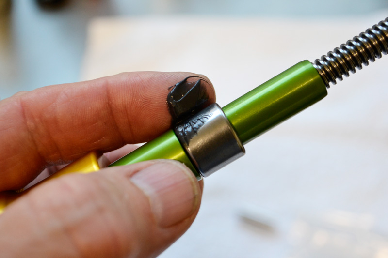
24) The aluminum
spacers have rubber
seals installed into
them. Put a light coat
of grease on these
seals and place them
onto each side of the
inner ring.
25) Put some blue
Loctite Threadlocker on the threads of
the shock mounting
bolt.
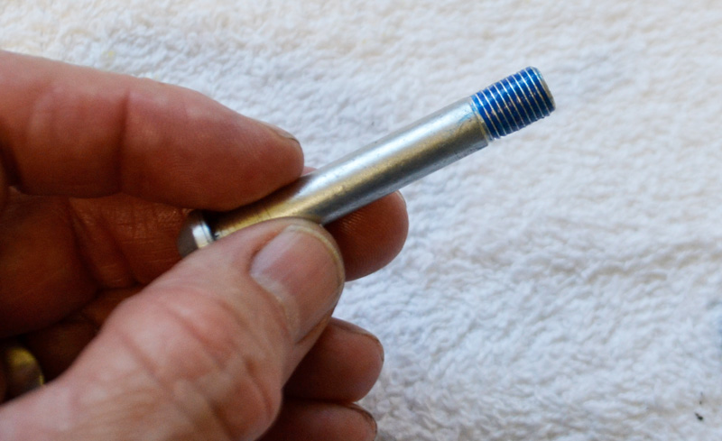
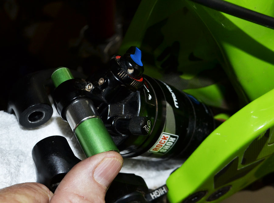
26) Raise the rear triangle
of the frame to align the
shock with the DELTA Link
rocker arms and slide the
shock bolt into place.
27) Keeping everything
properly aligned, turn
the shock bolt clockwise and tighten until
you feel the shock bolt
bottom out.
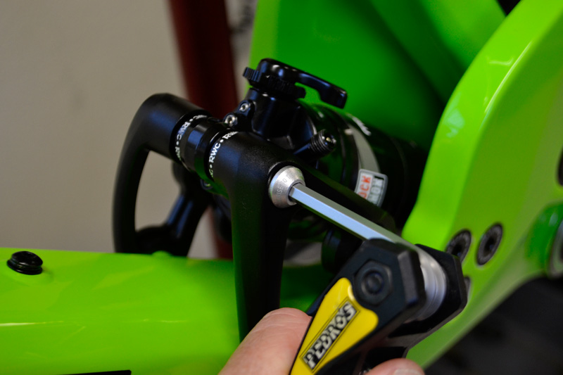
28) Proper torque spec
for the bolt is 10 N-m or
88 INCH-pounds.
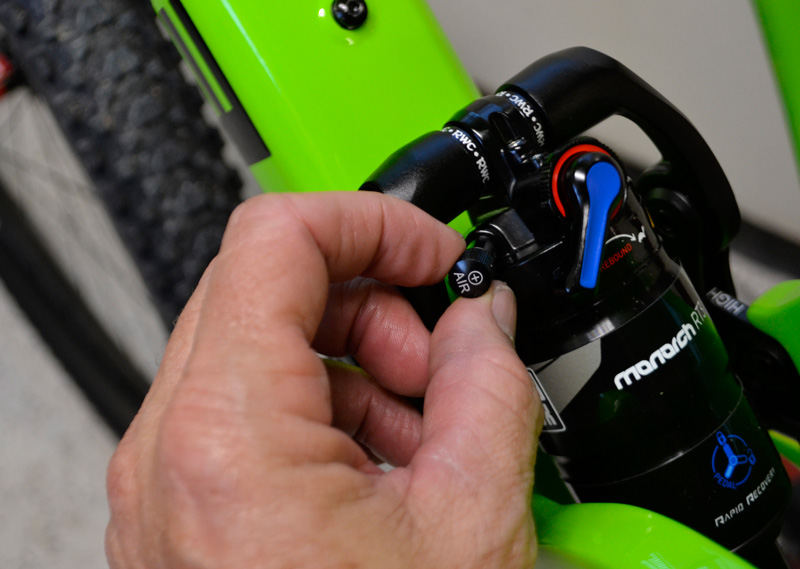
29) Air up the shock to your
previous setting, stopping at
stages to compress the suspension a few times in order
to equalize the positive and
negative air chambers.
You may find you need slightly more air pressure now that hardware-induced friction has been removed from the system.
30) Replace the air valve cap.
Note that for most of the DELTA Link applications, only the top mount is replaced with a
needle bearing kit. The lower shock mount has almost no rotation taking place inside the
shock eyelet. Where there is no rotation happening, a convention bushing is actually the best
choice.
IF you have previously made adjustments to your shock to dial in the best
performance, it is strongly suggested
that you re-analyze and make new adjustments since the old friction-bound
mounting hardware would have negatively affected shock performance.
Now that the excess friction has been
removed, a re-tune will result in much
better performance than you were
previously able to attain.
Please don't hesitate to contact us with any kit sizing questions or service part needs. Individual replacement parts are available. Our tools are designed to do the job quickly and easily without risk of damaging the parts or the shock. However, you are welcome to use whatever tools or improvised methods you prefer. Having said that, please be advised that we will not be responsible for the results of your improvised tools. If you do have any installation problems, you will find that we are willing to help you make things right regardless of where the fault lies. As with all of our products, satisfaction is guaranteed.